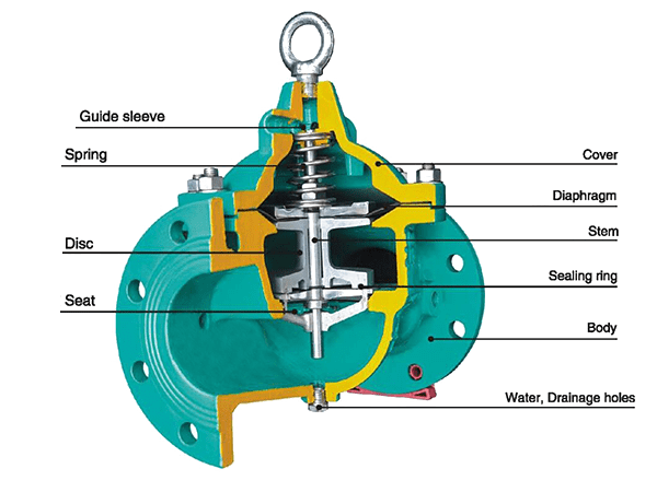
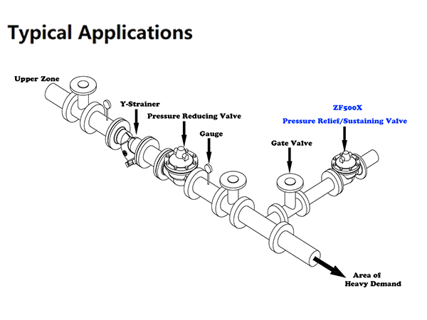
This valve is opened to prevent the pipeline and equipment from being damaged due to overpressure when the pressure in the water supply pipeline exceeds the set pressure of pressure relief. The valve closes automatically when pressure drops to the set value.

Accurate Pressure Control
Fast Opening to Maintain Line Pressure
Slow Closing to Prevents Surges
Completely Automatic Operation

Inlet pressure water enters the lower cavity of the pilot valve diaphragm from the guide valve when the pressure in the pipeline exceeds the set pressure of the guide valve to make its pressure increase to open the guide valve, the main valve control room outwards drain under the effect of the inlet pressure water to open the main valve, it starts to discharge pressure. When the pressure in the pipeline drops to the set pressure, the pressure in the lower cavity of the guide valve diaphragm decreases, causing the guide valve closed. This results in increased water pressure from the guide pipe to the pilot valve, then to the main valve control room. The main valve plate closes and begins to hold pressure.

The pressure relief(sustaining) valve supports horizontal and vertical installation but should pay attention to the inlet and outlet direction of valve body water when installing. In general, one fire water supply system can only install one pressure relief valve. Within the operating pressure range of the spring specified in the nameplate, the opening pressure can be adjusted by rotating the adjusting screw to change the spring compression amount. For specific use, please consult ZECO Valve Group.
Size Range: 2"~24"
Pressure Rating: 10bar ~ 25bar
Face to Face Dimensions: AMSE B16.10, EN558-1
Flange End Dimension: AMSE B16.1/16.42, AS4087, EN1092-2
Coating: Fusion Bonded Epoxy Coating
Inspection and Test: ISO 5208 / EN 12226-2
Part | Material | Standard |
Body | Ductile Iron | EN 1563/DIN 1693 |
Ductile Iron | EN 1563/DIN 1693 | |
Trim | Stainless Steel 431 | EN10088-1/ASTM A959 |
Seat | Stainless Steel 431 | EN10088-1/ASTM A959 |
Diaphragm | EPDM / NBR | ISO 4633 |
Pilot Valve | Stainless Steel 431 | EN10088-1/ASTM A959 |
For the materials options not listed, consult factory. ZECO manufactures valves in more than 50 different alloys. | ||
